How VM data is managed within an HPE SimpliVity cluster, Part 4: Automatic capacity management
This blog is the fourth in a 5-part series on VM data storage and management within HPE SimpliVity powered by Intel®.
The customers I talk to find HPE SimpliVity hyperconverged infrastructure extremely simple to use. They are savvy enough to know that that’s because there’s a lot going on behind the scenes, and they are technical enough to be curious about how it all works. Discovering the architectural ins and outs, and learning how data in a virtual machine is stored and managed in an HPE SimpliVity cluster can lead you to a better understanding of how data is consumed in your specific HPE SimpliVity environment, and how you can best manage it.

If you have been following this blog series, you know that I’m exploring HPE SimpliVity architecture at a detailed level, to help IT administrators understand VM data storage and management in HPE hyperconverged clusters.
Part 1 covered virtual machine storage and management in an HPE SimpliVity Cluster. Part 2 covered the Intelligent Workload Optimizer (IWO) and how it automatically manages VM data in different scenarios. Part 3 followed on, outlining options available for provisioning VMs.
Now in Part 4, I will cover how the HPE SimpliVity platform automatically manages virtual machines and their associated data containers after initial provisioning, as the VMs grow (or shrink) in size.
Note: The hyperconverged architecture is comparable in either VMware vCenter or Microsoft Hyper-V environments. For simplicity’s sake, I will focus on VMware environments in this post.
HPE SimpliVity Auto Balancer Service
The HPE SimpliVity Auto Balancer service is separate from IWO and the Resource Balancer service; however, its goal is the same: to keep resources as balanced as possible within the cluster.
Together, IWO and the Resource Balancer service are responsible for the provisioning of workloads (VM and associated data container placement). The Auto Balancer service is responsible for management of these data containers as they evolve in regards to overall node consumption (and cluster) consumption.
As I explained in Part 2 of this series, IWO keeps the VMware Distributed Resource Scheduler (DRS) aware of data location to help boost performance. IWO is aware of any changes that Auto Balancer carries out and will update VMware DRS affinity rules accordingly, should one or more data containers be relocated due to a node becoming space constrained.
How does it work?
The Auto Balancer service automatically migrates secondary data containers for any VM (except for VDI VMs) and associated backups to less utilized nodes should a node be running low on available physical capacity.

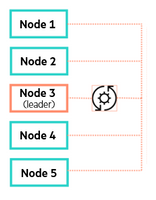
The Auto Balancer service runs on each node. One node in a cluster is chosen as a leader.
The leader may change over time or as nodes are added/removed from the cluster.
The Auto Balancer leader will submit tasks to other nodes to perform data container or backup migrations.
When will it operate?
The Auto Balancer service will not operate until a node is at least 50% utilized (in terms of capacity). As with IWO and the Resource Balancer service, Auto Balancer is also designed to be zero touch, i.e. the process is handled automatically. Remember, as previously covered, the Resource Balancer service handles the initial placement when the data container is created, the Auto Balancer handles the migration of these data containers if a node becomes space constrained.
A decrease in physical capacity on a node can be a result of the growth of one or more VMs, backups or the provisioning of more virtual machines into an HPE SimpliVity cluster.

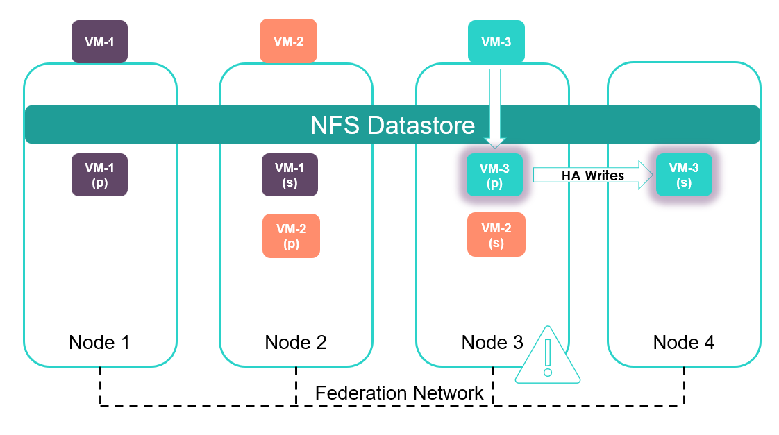
In the below illustration, VM-3’s on-disk data has grown by an amount that has caused Node 3 to become space constrained. The Auto Balancer service will now take a proactive decision to rebalance data across the cluster to try and achieve optimum distribution of data in terms of capacity and IOPS.Node 3 is full. As a result, Auto Balancer moves one or more data containers to balance the cluster.

In this example, Auto Balancer has elected to migrate VM-2’s secondary (standby) data container and its associated backups to Node 1. This process is handled automatically.The Auto Balancer service may or may not migrate the data containers that have grown.
The above illustration does not scale well when representing multiple nodes and virtual machines. It is easier to represent virtual machines and nodes in table format below; this format will also prove useful in the next post when I will share how to view data distribution across nodes for individual VMs and backups and how to manually balance this data if required.

Here is a second example to reinforce the lessons from the previous posts in regards to DRS, IWO and automatic balancing of resources.
For the sake of simplicity, the total physical capacity available to each node in the above table is 2TB. The physical OS space consumed after deduplication and compression for each VM is listed. For this example, backup consumption is omitted. Therefore, the cluster is relatively balanced with no nodes space constrained. Here is an overview:
- Total cluster capacity is 8TB (2TB x 4)
- Total consumed cluster capacity is 2.1TB ((50 + 300 + 400 + 300) x 2)
- Node 3 is currently the most utilized node, consuming 1TB of space
- DRS has chosen not to run any primary workload on Node 4
Now, imagine consumed space in Node 3 grows by 200GB and CPU and memory consumption also increases. The cluster is no longer balanced:
- Total cluster capacity remains at 8TB
- Total consumed cluster capacity is 2.5TB (50 + 300 + 600 + 300)
- Node 3 is currently over-utilized, consuming 1.2TB of space.
- An automatic redistribution of resources may move data such that it matches the table below.
DRS has chosen to run VM-4 on Node 4 due constrained CPU and Memory on Node 3, thus promoting VM-4’s standby data container to the primary data container.

The Auto Balancer service has migrated the secondary copy of VM-3 to Node 1 to rebalance cluster resources.
It is worth noting that other scenarios are equally valid, i.e., VM-4 secondary data container could also have been migrated to Node 1 for example (after the DRS move), which would have resulted in roughly the same redistribution of data.
Viewing the status of auto balancer
The command “dsv-balance-show –shownodeIP“ command shows the current cluster leader.

Here the current leader is OVC 10.20.4.186
The log file balancerstatus.txt shows submitted tasks and status on the leader node. In other words, this txt file is only visible from the leader node.

Issue the command “cat /var/svtfs/0/log/balancerstatus.txt” to view the status of any active migrations.The output of this file shows the migration of backup from Node 1 to Node 2.
Another handy command is ‘dsv-balance-migration-show – showVMName’ which was introduced in version 3.7.7. This is cluster wide command so it can be run from any node in the cluster. This will list the Virtual Machine being migrated along with the host it has been migrated from and too.
Note: Currently the Auto Balancer does not support the migration of remote backups.
Closing thoughts
The HPE SimpliVity Intelligent Workload Optimizer (IWO) and Auto Balancer features balance existing resources, but cannot create resources in an overloaded cluster. In some scenarios, manual balancing may be required. The next post will explore some of these scenarios, how to analyze resource utilization and manually balance resources within a cluster if required.
More information about the HPE SimpliVity hyperconverged platform is available online:
- HPE SimpliVity Data Virtualization Platform provides a high level overview of the architecture
- You’ll find a detailed description of HPE SimpliVity features such as IWO in this technical whitepaper: HPE SimpliVity Hyperconverged Infrastructure for VMware vSphere


![picture2-1555105142615[1] picture2-1555105142615[1]](https://builddaylive.com/wp-content/uploads/2019/05/picture2-15551051426151-1024x255-394x330.png)